
A new energy meter should not be accepted simply because its display turns on or a dashboard starts receiving data. Commissioning is the process of proving that the meter has the correct system configuration, that each voltage channel is paired with the right current transformer, that import and export directions are correct, and that the values remain credible from the meter terminals through to the final monitoring platform.
For a simple single-phase monitor, this may take 15 to 30 minutes. For a three-phase, CT-operated submeter connected through Modbus, a disciplined commissioning check can prevent months of bad data, incorrect cost allocation, false solar export, misleading power-factor alarms, and difficult disputes between installers, operators, tenants, or energy managers.
This guide provides a practical acceptance workflow for monitoring and submetering projects. Work inside energized switchboards must be performed only by qualified personnel using the required isolation, test equipment, personal protective equipment, and local safety procedures.
What a successful commissioning result should prove
Before the meter is handed over, the project team should be able to answer all of the following with evidence:
- Is the meter configured for the actual electrical system: single-phase, three-phase four-wire, or three-phase three-wire?
- Do the configured CT and voltage-transformer ratios match the installed hardware?
- Is the L1 voltage channel paired with the L1 current input, and likewise for L2 and L3?
- Are CT primary direction and secondary polarity correct?
- Does positive or negative power mean what the project specification says it means?
- Are voltage, current, power factor, active power, reactive power, frequency, and energy plausible?
- Does the meter agree reasonably with an independent instrument under a stable load?
- Do Modbus, pulse, Ethernet, Wi-Fi, or gateway outputs preserve the same values and units?
- Does the upstream platform treat import, export, demand, and accumulated energy correctly?
- Is there a commissioning record detailed enough for another technician to reproduce the result?
A meter can pass some of these checks and still fail the installation. For example, total current may look plausible while L2 current is paired with L3 voltage, producing incorrect real power and power factor. Similarly, a dashboard can show a smooth graph even when the CT ratio is wrong by a factor of five.
Start with the design, not the display
Collect the approved single-line diagram, meter model and firmware, CT datasheets, communication map, and the intended measurement boundary before energization. Record the following configuration values:
| Item | What to record | Why it matters |
|---|---|---|
| Network type | 1P2W, 3P4W, 3P3W or other supported form | Determines how the meter calculates phase and total values |
| Nominal voltage and frequency | Site values and meter limits | Detects an incompatible product or incorrect setup |
| CT ratio | Primary and secondary rating for every CT | A wrong ratio scales current, power and energy incorrectly |
| VT/PT ratio | Primary and secondary values, if used | A wrong ratio scales voltage, power and energy |
| Phase assignment | L1/L2/L3 voltage and current input mapping | Prevents cross-phased power calculations |
| Energy convention | Import/export and positive/negative definitions | Avoids reversed billing or solar-flow interpretation |
| Communications | Address, baud rate, parity, IP settings and unit ID | Makes field and platform configuration reproducible |
| Register units | W or kW, Wh or kWh, signed or unsigned | Prevents integration-side scaling errors |
| Time settings | Time zone, clock and interval boundary | Keeps interval data aligned with tariffs and other systems |
ABB's D1M 20 installation documentation, for example, treats network type, CT ratio and VT ratio as mandatory first-commissioning settings. That is a useful general principle even when another meter uses different menu names.
If the project uses CTs, also verify the information discussed in How to Choose the Right CT Clamp for Energy Metering. The installed CT ratio, output type, burden requirements and conductor size must match the meter input; commissioning cannot correct incompatible hardware.
Perform a safe de-energized inspection first
A physical inspection should occur before live measurements. Check the installation against the manufacturer's wiring diagram and the approved design, not against memory or conductor colour alone.
Confirm:
- Voltage inputs are protected as required by the meter manufacturer and local rules.
- Each voltage input is connected to the intended phase and neutral.
- Each CT surrounds only the intended conductor, not a multicore cable containing both outgoing and return paths.
- Split-core CTs are fully closed, clean at the mating surfaces, mechanically secure and not forced around an oversized conductor.
- CT primary direction marks such as P1/P2, K/L, source/load, or an arrow are consistent with the defined import direction.
- CT secondary conductors land on the correct current input with the intended S1/S2 or k/l polarity.
- CT secondary wiring is segregated, identified and terminated according to the manufacturer's requirements.
- Shorting links or test blocks are in the correct operating position.
- Communication shielding, termination and earthing follow the network design.
- Terminal torque, clearances, enclosure rating and access controls meet the project and manufacturer requirements.
Never open-circuit the secondary of a conventional current-output CT while primary current is flowing. Use the specified shorting arrangement and safe work procedure. Voltage-output split-core sensors and Rogowski coils have different rules, so follow the exact sensor documentation rather than applying a generic CT procedure.
Verify the configured ratios before applying load
A ratio error often creates believable but consistently wrong data. A 400/5 A CT entered as 200/5 A will make the meter report roughly half the actual current, power and energy. A meter configured for a 1 A secondary when a 5 A CT is installed may produce a much larger error or exceed its intended input.
Check the configuration at the meter and, where possible, export or photograph the settings. Do not rely only on a commissioning laptop profile because a previous configuration may not have been written successfully.
For each CT channel, record:
- manufacturer and model;
- primary rating;
- secondary rating or output;
- accuracy class;
- installed phase;
- polarity orientation;
- meter input number;
- configured ratio.
If accuracy matters for cost allocation, carbon reporting or performance guarantees, read Energy Meter Accuracy Classes Explained: Class 0.5S vs Class 1. The installed system accuracy includes more than the meter nameplate: CT accuracy, wiring, burden, operating current and installation quality also matter.
Energize and check voltage before trusting power
After the required safety checks and authorization, energize the voltage circuit and inspect phase-to-neutral and phase-to-phase readings. Compare them with an appropriate reference instrument at a safe test point.
Look for:
- one phase at zero or much lower than the others;
- an implausible phase-to-phase relationship;
- frequency outside the expected range;
- phase order alarms;
- a network type that does not match the displayed voltage set;
- unstable readings caused by a loose or intermittent voltage reference.
Balanced voltage does not prove that phase mapping is correct. L1, L2 and L3 may all be present but assigned to the wrong meter inputs. That mistake becomes visible only when current and phase angle are considered together.
Apply a known, stable load one phase at a time
The most useful commissioning test is a controlled load whose phase and approximate power are known. Where the site design permits, switch on one stable load at a time and observe which meter channel changes.
For each test:
- Note the baseline current and power on all phases.
- Energize the known load.
- Confirm that the expected phase current rises.
- Confirm that active power changes in the expected direction.
- Compare the change with the load nameplate or an independent clamp meter.
- Remove the load and confirm that the values return close to baseline.
- Repeat for the other phases.
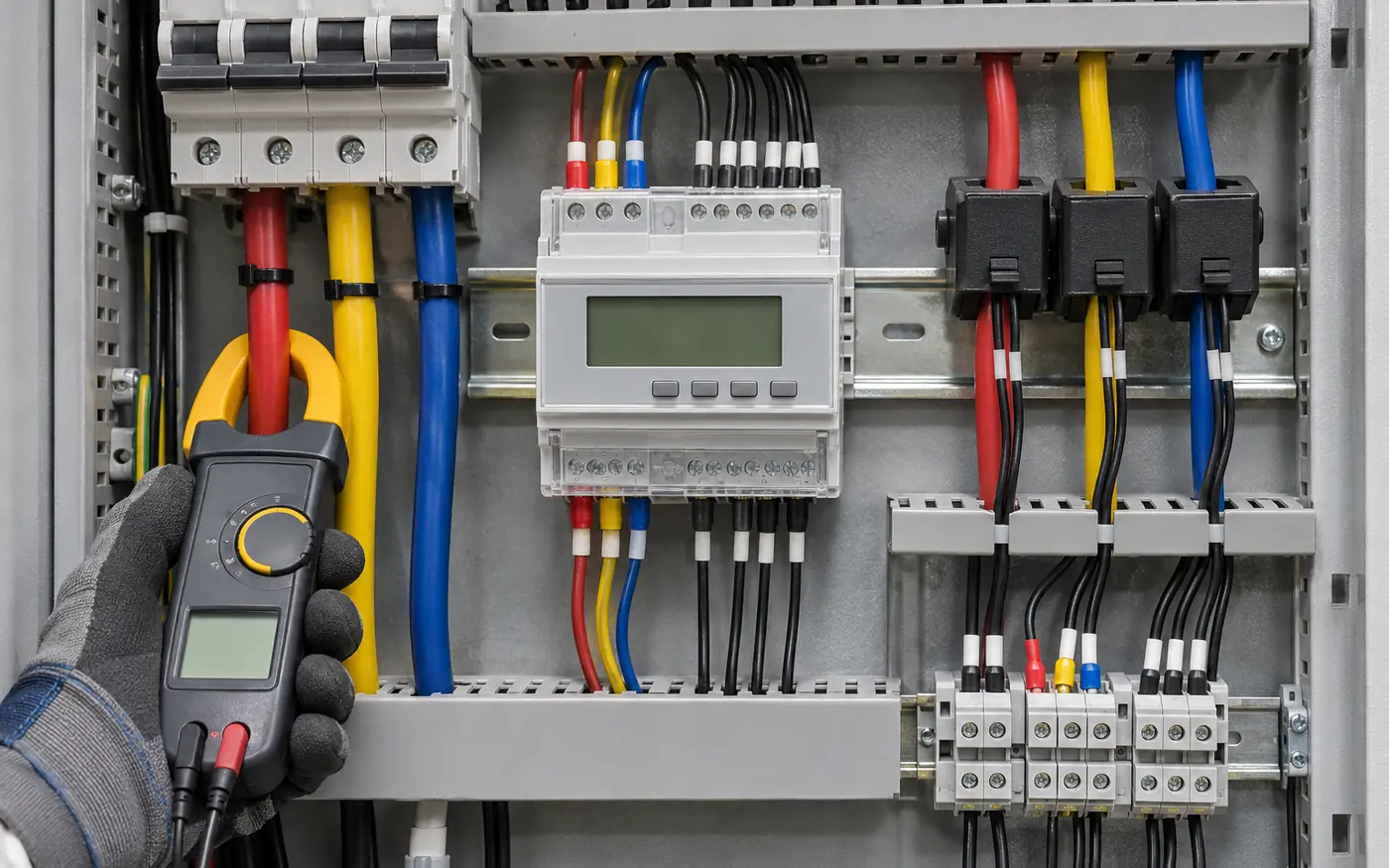
Comparing a stable phase current with an independent instrument helps expose ratio, channel and scaling errors. The image is illustrative; test methods must follow site safety rules.
A resistive load is convenient because its power factor is usually close to unity, making the expected relationship between voltage, current and active power easier to interpret. Variable-speed drives, motors, inverters, UPS systems and lightly loaded transformers can have more complex waveforms and power factors, so they are less suitable as the first proof load.
The reference instrument and the meter do not need to match perfectly. Their accuracy classes, sampling windows, conductor position, waveform response and display update rates may differ. The goal is to identify a material discrepancy, not to perform laboratory calibration with a handheld clamp meter.
Use phase power and power factor to find cross-phasing
A common three-phase error occurs when a current channel is paired with the wrong voltage channel. The current magnitude can still be correct, but calculated active power may be too low, negative or accompanied by an implausible power factor.
Typical warning signs include:
- one or more phases showing negative active power on a known importing load;
- power factor near zero on a stable resistive load;
- similar current on each phase but very different active power;
- total kVA that looks reasonable while total kW is unexpectedly low;
- phase reactive power with an unexpected sign;
- phase values that change on the wrong circuit during a controlled-load test.
A phasor diagram is especially valuable here. Schneider Electric's PowerLogic documentation notes that a phasor viewer can be used to verify or troubleshoot voltage and current input wiring, including polarity. In a correctly mapped balanced three-phase system, voltage phasors should have the expected sequence and the associated current phasors should sit at credible angles for the connected loads.
Do not correct a physical wiring error only by applying a software polarity inversion unless the meter manufacturer allows it, the project standard accepts it, and the final documentation clearly records the correction. A hidden software fix can confuse the next technician and may be lost during replacement or factory reset.
Confirm import and export direction deliberately
Sites with solar, batteries, generators, regenerative drives or bidirectional EV charging require an explicit direction test. The words "positive", "negative", "import" and "export" are not universal across every device and integration.
Create at least two known operating states if the system permits:
- Known import: site load exceeds local generation, so power flows from the grid or upstream source toward the load.
- Known export: local generation exceeds site demand, so power flows toward the grid or upstream bus.
For each state, record the meter's phase power, total power, import register and export register. Then check the same values in the gateway and final application. A platform may invert a signed register, swap import/export entities, or apply a template written for another meter.
If the readings are reversed, work through the chain in order:
- CT primary direction;
- CT secondary polarity;
- voltage-current phase pairing;
- meter polarity settings;
- register interpretation;
- gateway transformation;
- application entity mapping.
The troubleshooting guide Why Your Energy Monitor Shows Negative Power explains these direction errors in more detail.
Validate total power with a simple engineering check
Use a quick independent calculation as a reasonableness test.
For a single-phase circuit:
Approximate real power = voltage × current × power factor
For a reasonably balanced three-phase load:
Approximate real power = 1.732 × line-to-line voltage × line current × power factor
For an unbalanced three-phase four-wire system, calculate each phase separately and add the results. This is usually more reliable than forcing the balanced formula onto a real building load.
Example: a balanced 400 V three-phase load drawing 20 A at 0.90 power factor should be near:
1.732 × 400 × 20 × 0.90 = 12.5 kW
If the meter reports 2.5 kW, 25 kW or a negative value, investigate the CT ratio, phase mapping and polarity before accepting the point. If it reports 12.1 kW or 12.8 kW, consider instrument accuracy, load stability and waveform conditions before declaring a fault.
Check energy accumulation, not only instantaneous power
Instantaneous readings can look correct while accumulated energy uses the wrong scale or register. Run a stable load for a measured period and compare the change in the energy register with the expected result.
For example, a stable 10 kW load running for 30 minutes should add approximately 5 kWh. Allow for load variation and instrument accuracy, but investigate errors of 10×, 100× or 1000× immediately; these often indicate Wh/kWh scaling or register-decimal mistakes.
Confirm that:
- import energy increases during import;
- export energy increases during export;
- the wrong register does not increase at the same time;
- energy survives a meter or gateway restart as designed;
- rollover and reset behavior are understood;
- interval totals reconcile reasonably with register changes;
- demand windows align with the tariff or reporting requirement.
For revenue-grade or regulated billing, a field reasonableness test is not a substitute for the required certified meter, seals, test equipment, procedures and legal metrology controls.
Commission the communications path separately
Once the local display is credible, verify every downstream hop. Compare the meter display with raw communication values before checking the dashboard.
For Modbus RTU or TCP, document:
- slave or unit ID;
- baud rate, data bits, parity and stop bits;
- IP address, port and gateway path where applicable;
- register address and whether documentation uses zero-based or one-based notation;
- data type, word order and byte order;
- signed versus unsigned interpretation;
- multiplier and unit;
- polling interval and timeout;
- exception and stale-data handling.
Read current, voltage, active power and accumulated energy from the raw register layer and compare them with the meter display at nearly the same time. A value that is correct locally but wrong in software is usually an integration problem, not a CT problem.
For RS-485 networks, also verify termination, biasing, shield practice, device addressing and cable topology. The guide Do You Need an RS485 to Ethernet Gateway for Home Energy Monitoring? covers the architectural trade-offs.
Test timestamps, intervals and missing-data behavior
Energy data is valuable only when it is attached to the correct time. Confirm the meter, gateway and platform time zones, daylight-saving behavior and clock synchronization.
Create a short controlled event, such as switching a known load on for five minutes, and verify that:
- the event appears in the correct interval;
- the timestamp is not shifted by one hour or one day;
- the platform does not double-count cumulative energy;
- missing polls create a gap or quality flag rather than a false zero;
- the dashboard distinguishes live power from interval energy;
- tariff periods align with the intended local time.
A smooth chart is not proof of correct interval processing. Some platforms interpolate missing data, repeat the last value, or convert a cumulative register into interval energy incorrectly.
Use a commissioning checklist and evidence pack

A reproducible handover record should connect the physical installation, meter settings, field measurements and final platform values.
A useful commissioning record should include:
- site, panel and circuit identification;
- meter make, model, serial number and firmware;
- CT make, model, ratio, class and phase assignment;
- wiring configuration and ratio settings;
- photos of CT orientation, terminals and equipment labels where permitted;
- voltage, current, power, power factor and frequency for each phase;
- controlled-load test results;
- import/export direction test results;
- phasor screenshot or phase-angle record if available;
- raw communication values and register mapping;
- dashboard screenshots with timestamps;
- energy accumulation test;
- deviations, corrective actions and retest results;
- names, dates and approval signatures;
- next verification date and responsible owner.
Avoid storing sensitive network credentials in a general handover report. Keep passwords and security keys in the organization's approved credential system.
Common failures and the quickest next check
| Symptom | Likely causes | First useful check |
|---|---|---|
| Current is correct but kW is wrong | Cross-phasing, poor power factor, wrong voltage reference | Apply a resistive load and inspect phase power/phasors |
| All values are consistently too high or low | CT/VT ratio or software multiplier | Compare configured ratio with hardware nameplate |
| One phase shows negative power | Reversed CT or mismatched voltage/current phase | Verify phase assignment and CT polarity |
| Total power is near zero with load present | Opposing phase signs or summation error | Inspect per-phase active power |
| Solar export appears as consumption | Direction convention reversed | Run known import and export states |
| Local display is right, dashboard is wrong | Register, data type, scaling or unit error | Compare raw registers with local display |
| Random spikes or dropouts | Communications noise, loose wiring or parsing error | Check logs, cabling, termination and raw data |
| Energy is 1000× wrong | Wh/kWh or W/kW mismatch | Verify units at every system boundary |
| Timestamps are shifted | Time zone or daylight-saving mismatch | Create a timed load event |
| Readings changed after maintenance | CT moved, polarity reversed or settings reset | Repeat physical inspection and load test |
When should the meter be re-verified?
Commissioning is the baseline, not the final lifetime check. Re-verify the installation after:
- switchboard or circuit modifications;
- CT replacement or conductor relocation;
- meter, gateway or firmware replacement;
- communication-map changes;
- solar, battery, generator or EV charger additions;
- unexplained changes in power factor, phase balance or energy totals;
- a billing or tenant-allocation dispute;
- a long communications outage;
- the periodic interval required by the site's quality plan.
At minimum, compare monthly meter totals with another credible source and investigate abrupt changes in the relationship. A stable ratio between two meters is often more informative than expecting exact agreement from devices with different measurement boundaries.
A practical acceptance sequence
For most three-phase monitoring projects, the following order is efficient:
- Review the design and define the measurement boundary.
- Record meter, CT and communication details.
- Perform de-energized wiring and polarity inspection.
- Confirm network type and ratio settings.
- Energize and validate voltage and frequency.
- Apply known loads and confirm phase mapping.
- Check power factor, phasors and polarity.
- Prove import and export direction where relevant.
- Compare current and power with an independent instrument.
- Run an energy accumulation test.
- Validate raw communications and software scaling.
- Verify timestamps, intervals and missing-data behavior.
- Save evidence, corrective actions and final approval.
- Set a re-verification date.
A meter is ready for operational use when the physical installation, local display, communication registers and final application tell the same coherent story. If they do not, stop at the first layer where the values diverge; that is usually where the fault lives.