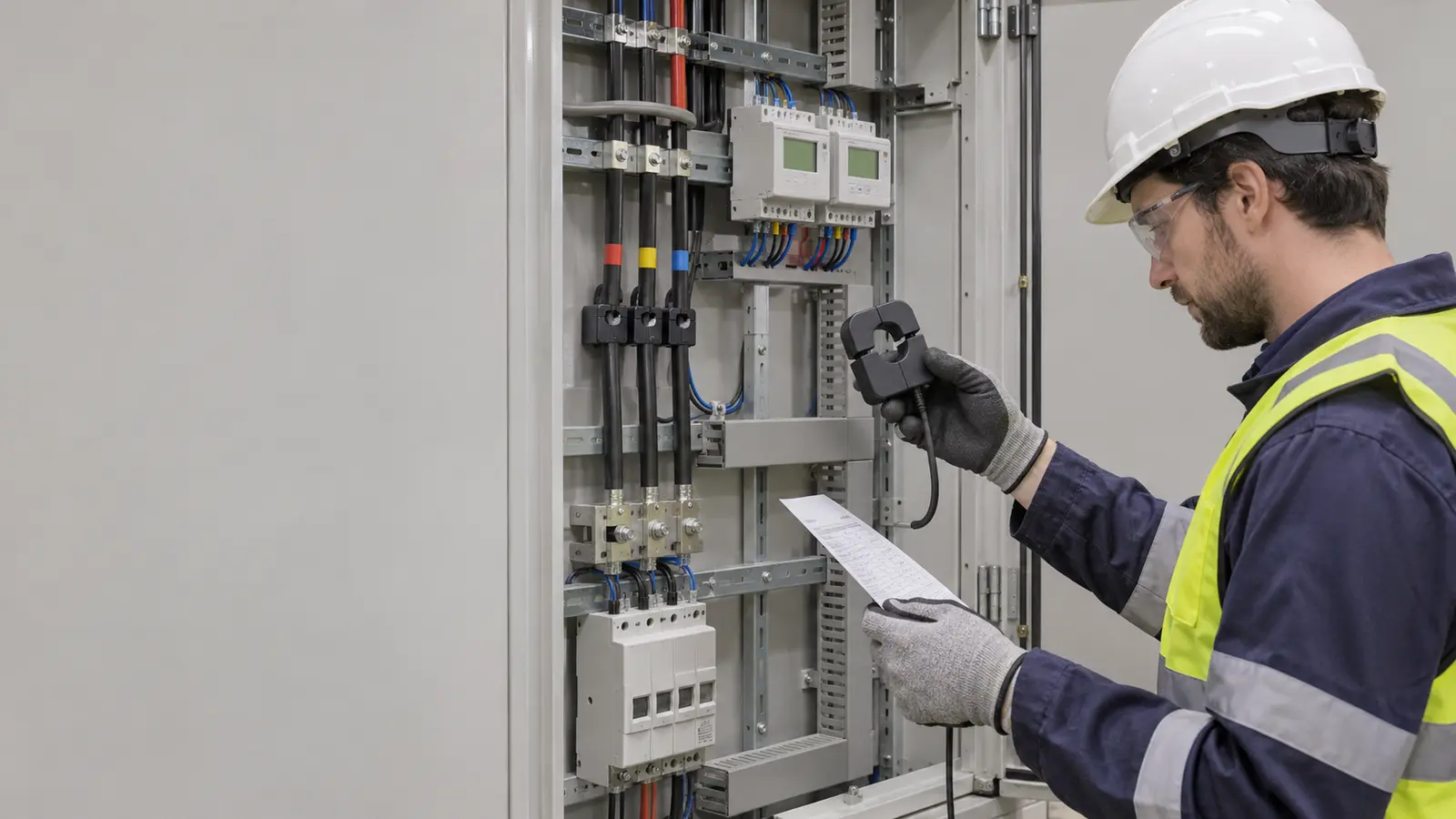
A current transformer (CT) is easy to underestimate. It looks like a simple sensor around a cable, yet the wrong CT can make an otherwise capable energy meter report inaccurate, reversed or unusable data.
The best CT is not simply the one with the highest current rating or the smallest accuracy number. It must match the meter input, the expected current range, the conductor or busbar, the installation method and the complete secondary circuit. For three-phase metering, every CT must also remain paired with the correct voltage phase.
This guide provides a practical selection and commissioning workflow for facility energy monitoring, solar import/export measurement, tenant submetering and industrial load analysis.
Safety note: CTs are installed in or near energized electrical equipment. Selection, installation and servicing should be performed by a qualified electrical professional under the applicable local rules and the instructions for the exact meter and CT. De-energize and verify isolation before work whenever required. A conventional 1 A or 5 A CT secondary must never be left open while primary current is flowing.
Quick answer: choose a CT in this order
- Match the meter input exactly. Confirm whether the meter accepts 1 A, 5 A, 333 mV, another mV/mA signal or a Rogowski-coil input.
- Choose the primary current rating. Select a ratio that covers the real maximum current without oversizing so far that normal loads sit in a weak part of the measurement range.
- Check the opening and external dimensions. The conductor or busbar must fit with enough space to close, mount and route the CT safely.
- Choose solid-core or split-core construction. Solid-core CTs suit new work where the conductor can be disconnected; split-core CTs are usually easier for retrofits.
- Check accuracy across the useful load range. The class label, rated burden and low-current performance all matter.
- Calculate the secondary burden where applicable. Include the meter input, terminal blocks and the resistance of both secondary leads.
- Plan polarity and phase pairing. Mark each CT, conductor and meter channel before commissioning.
- Verify the complete installation. Compare current, power direction, phase assignment and accumulated energy against an independent reference.
This sequence prevents a common procurement error: choosing a CT from its current ratio alone and discovering later that it cannot connect to the meter, fit the panel or meet the required accuracy.
Start with the meter, not the CT
The meter input defines the type of secondary signal it can interpret. Common options include:
| Meter input | Typical CT output | What to confirm |
|---|---|---|
| 5 A current input | 100/5 A, 200/5 A, 400/5 A and similar | Rated burden, lead resistance and provision for safe shorting |
| 1 A current input | 100/1 A, 200/1 A and similar | Exact 1 A compatibility and meter ratio settings |
| Low-voltage input | Commonly 333 mV at rated primary current | Exact voltage rating, polarity and approved CT family |
| Low-current input | 80 mA, 100 mA, 200 mA or vendor-specific | Exact output and input match |
| Rogowski input | Coil plus integrator or compatible meter input | Coil rating, integrator requirement, frequency and phase performance |
A 333 mV CT is not an interchangeable replacement for a 5 A CT, even if both carry the same primary-current label. Likewise, connecting a 5 A secondary to a 1 A input can exceed the input rating. The meter manual and CT datasheet must agree on output type, nominal value and wiring.
Accuenergy's CT label guide, for example, shows that the primary value and secondary value must both be configured in the meter; its product range includes 1 A, 5 A, mA and 333 mV variants. That variety is useful, but it also makes “a 200 A CT” an incomplete specification.
Choose a primary rating that reflects real current
A CT ratio such as 200/5 A means that 200 A in the primary conductor produces the rated 5 A secondary current under its specified conditions. For a 333 mV device, the same idea applies: rated primary current produces the rated voltage output.
The primary rating needs to cover the highest credible operating current, including expected expansion. However, larger is not automatically better. If a site normally operates at 12-35 A, choosing an 800 A CT merely because it fits can leave most readings near the bottom of its range. Ratio error and phase displacement at low current may then dominate energy and power-factor results.
Use these inputs:
- the protective-device and conductor rating;
- measured peak current from a representative period;
- motor or transformer operating characteristics;
- planned EV charging, heat pumps, solar or process expansion;
- the meter's overload capability and the CT's specified measurement range;
- the minimum current at which useful accuracy is required.
For a new installation with no interval history, use the electrical design and realistic diversity assumptions rather than summing every nameplate load as though all equipment runs at full power continuously. For an existing site, a temporary logger or qualified clamp-meter survey can reveal both the usual range and genuine peaks.
Schneider Electric's general selection guidance recommends choosing a ratio that encompasses the application and then checking the window, application, accuracy and burden. Treat that as a sequence, not permission to select an arbitrarily large ratio.
Check the CT window and the whole physical envelope

Window size is a hard constraint. Confirm the actual outside diameter of an insulated conductor, the width and thickness of a busbar, and any bend radius or termination that the CT must pass. Then check the CT's external width, depth, hinge movement, latch access and lead exit.
A technically correct aperture can still be impractical when:
- adjacent phases leave no room for the CT body;
- the split core cannot open fully inside the enclosure;
- the latch faces a wall or gland plate;
- cable bends push the core halves apart;
- the CT cannot be fixed against vibration;
- secondary leads cross sharp edges or energized parts.
Allow installation clearance rather than specifying an opening that only fits on paper. For crowded branch-circuit panels, compact hinged CTs may be more workable than a large removable-top design. For busbars, select a shape intended for bars rather than forcing a round-window CT into an awkward position.
Each CT normally surrounds one phase conductor. Do not place both the outgoing and returning conductors of a single-phase circuit inside the same ordinary CT: their magnetic fields oppose one another, so the reading will approach the residual difference instead of the load current.
Solid-core vs split-core CTs
Solid-core CTs form a continuous magnetic core. They can offer a compact, stable measurement path and are a natural choice in new switchboards where the primary conductor can be routed through the core during assembly. Their disadvantage is installation disruption: an existing conductor or busbar connection usually has to be disconnected.
Split-core CTs open around an existing conductor. They are well suited to retrofit energy monitoring and staged deployments because installation can be less disruptive. Their mating surfaces, latch and mounting still matter. Dirt, a partially closed core, mechanical strain or poor alignment can affect performance.
Choose based on the project:
- New switchboard with accessible conductors: consider solid-core.
- Retrofit where conductor disconnection is costly: consider split-core.
- Crowded branch circuits: consider a compact hinged split-core model.
- Large or irregular busbars: consider a purpose-built rectangular split-core CT or an approved alternative such as a compatible Rogowski coil.
- Billing-grade or contractual measurement: verify that the entire metering system and installation meet the required regulatory and accuracy rules; a convenient CT alone does not establish compliance.
The selection should also consider insulation rating, measurement category, pollution degree, indoor or outdoor rating, temperature range and the maximum system voltage. These are safety and reliability requirements, not optional catalog details.
Accuracy class is only part of system accuracy
A Class 0.5, Class 0.5S or Class 1 label describes performance under defined standard conditions. It does not guarantee that an installed system will stay within that percentage at every current, burden, power factor and wiring arrangement.
The useful questions are:
- At what percentages of rated current is the accuracy specified?
- Is both ratio error and phase displacement specified?
- Does the claimed class apply to the exact ratio and output variant?
- What burden range is required?
- Is the CT intended for measurement or protection?
- Does the energy meter add another accuracy contribution?
- Will the site spend most of its time at low current?
Class 0.5S can be valuable for variable-load sites where low-current energy matters, while Class 1 may be adequate for operational monitoring. The decision should follow the use case: trend visibility, cost allocation, billing verification and legal metrology do not carry the same requirement.
For a deeper explanation, see Energy Meter Accuracy Classes Explained: Class 0.5S vs Class 1.
Understand burden and lead length
For traditional 1 A and 5 A CT circuits, the secondary burden includes the meter input, secondary wiring, terminal blocks, test switches and other series elements. If the actual burden falls outside the CT's specified range, ratio and phase performance may no longer meet the stated class.
For the resistive part of the circuit:
Burden in VA = secondary current² × loop resistance
That square term is important. With the same loop resistance, a 5 A secondary produces 25 times the wiring loss of a 1 A secondary. Schneider Electric notes this relationship when recommending 1 A secondaries, larger conductors or shorter leads where burden is excessive.
A practical burden check is:
- Find the CT's rated burden and permitted accuracy range.
- Find the meter's current-input burden from its datasheet.
- Calculate the resistance of the complete outgoing-and-return secondary lead.
- Include terminal blocks and test equipment where relevant.
- Convert the total into VA at rated secondary current.
- Confirm that the result satisfies both CT and meter documentation.
Do not apply a 1 A/5 A burden calculation blindly to every sensor. Many low-voltage-output CTs contain an internal burden resistor and are specified by output voltage, lead limits and meter input requirements instead. Follow the documentation for the exact sensing technology.
Keep polarity and voltage phase paired

Power is calculated from voltage and current together. In a three-phase system, the CT on L1 must feed the current channel associated with the L1 voltage input; the same rule applies to L2 and L3. A correct CT ratio cannot compensate for crossed phases.
Polarity markings vary. You may see P1/P2 and S1/S2, H1/H2 and X1/X2, K/L, or an arrow. Manufacturers do not all use identical lead colours, so use the specific datasheet rather than memory. Define a site convention, such as source-to-load, before installation and apply it to every phase.
Typical symptoms of a polarity or phase-pairing error include:
- negative active power on a consuming feeder;
- export shown while the site is clearly importing;
- implausible power factor;
- one phase appearing to generate while the others consume;
- correct-looking current but incorrect total kW;
- solar production and grid exchange moving in the wrong relationship.
A negative reading is not automatically an error on a bidirectional solar connection. The test must begin with a known operating state and a documented sign convention. Why Your Energy Monitor Shows Negative Power explains how to separate valid export from reversed sensing.
Safety: never treat CT leads as harmless signal wires
Conventional current-output CTs can develop dangerous secondary voltage if the secondary circuit is opened while primary current flows. Schneider Electric states that these CTs must remain connected to a burden or be safely shorted; appropriate shorting blocks are used for installation and servicing.
This leads to several non-negotiable practices:
- isolate primary equipment where required before installation;
- never disconnect a live 1 A or 5 A secondary without the approved shorting procedure;
- use rated shorting/test terminals where the design requires serviceability;
- do not fit improvised connectors;
- maintain insulation, separation and enclosure requirements;
- label the CT ratio, phase, polarity and destination meter channel;
- follow the meter and CT manufacturer instructions even when they differ from a previous project.
Some 333 mV and mA systems do not use the same shorting arrangement as 1 A/5 A circuits. That does not make panel work safe for unqualified installation. It means the service procedure must match the sensor technology.
A worked selection example
Consider a three-phase commercial site with these design inputs:
- existing 160 A main protection;
- measured normal current of 35-95 A per phase;
- recorded peaks of 122 A;
- planned load growth that could lift peaks to about 140 A;
- an energy meter with 5 A current inputs;
- a 6 m one-way secondary cable route;
- a retrofit installation with no practical conductor disconnection.
A sensible shortlist might begin with 150/5 A or 160/5 A split-core measurement CTs, subject to the manufacturer's continuous-current and overload ratings. A 400/5 A model would provide ample headroom but could place ordinary operation unnecessarily low in the range.
The engineer would then:
- measure each insulated conductor and panel clearance;
- select a split-core window and housing that can close and be secured;
- check accuracy at the expected 35-95 A operating band;
- obtain the meter input burden and calculate the full secondary-loop burden;
- confirm whether the cable length and conductor size remain within the CT's rated VA;
- specify a shorting/test block and labels;
- confirm voltage category, insulation and environmental ratings;
- document CT ratio and phase mapping in the commissioning sheet.
This is an illustrative method, not a project specification. Fault levels, protective requirements, local codes and the actual equipment documentation can change the correct choice.
Commissioning checklist
A CT installation is not finished when the enclosure closes. Verify it under controlled, known conditions.
Visual and configuration checks
- CT ratio and output match the purchase schedule and meter input.
- Each core is fully closed and mechanically secure.
- Each CT surrounds only the intended conductor.
- Polarity is consistent with the documented direction.
- L1, L2 and L3 CTs match their voltage inputs.
- Secondary wiring is identified at both ends.
- Meter ratio, wiring mode and system type are configured correctly.
- Test/shorting terminals are in their normal operating state.
- CT leads are routed and protected as specified.
Live functional checks by a qualified person
- Compare phase current with a calibrated or suitable reference instrument.
- Apply or identify a stable load and confirm that the correct phase changes.
- Confirm active-power sign under known import and, where applicable, export.
- Check that total kW is plausible from voltage, current and power factor.
- Inspect power factor for phase-pairing errors.
- Confirm that accumulated kWh increases in the expected register.
- Review readings at both low and higher loads rather than testing at one point only.
- Record the date, load condition, reference instrument and result.
For solar systems, also perform a known nighttime import check and a daytime export check when conditions permit. For more installation failure modes, see How to Avoid the Most Common CT Clamp Mistakes.
Common CT selection mistakes
Buying by maximum amps alone
The CT fits the current rating but not the meter input, conductor or accuracy requirement.
Oversizing “for safety”
Excessive ratio headroom can weaken low-load visibility. Future expansion should be realistic and documented.
Ignoring the CT housing
The window fits the cable, but the body collides with the next phase or cannot latch.
Mixing CT families
Three devices may share a nominal ratio while having different phase error, output or polarity conventions. Use a matched, approved set unless the system design explicitly supports otherwise.
Forgetting secondary burden
Long thin leads on a 5 A circuit can consume the available VA and move the installation outside its accuracy conditions.
Pairing current with the wrong voltage phase
Current readings look plausible, yet kW and power factor are wrong because L1 current is calculated with L2 voltage.
Assuming a class label covers the full installation
The CT, meter, wiring, configuration and commissioning all contribute to the result.
Procurement checklist
Before issuing a purchase order, record:
- application: operational monitoring, submetering, allocation or billing;
- system voltage, frequency and wiring arrangement;
- primary current range and expected normal-load band;
- CT ratio;
- output type and nominal value;
- meter make, model and input specification;
- accuracy class and the current/burden range over which it applies;
- rated burden or compatible low-voltage input requirement;
- conductor diameter or busbar dimensions;
- CT window and complete external dimensions;
- solid-core, split-core or hinged construction;
- cable length, termination and shorting/test requirements;
- insulation, measurement category and environmental ratings;
- mounting method and lead routing;
- phase and polarity labels;
- certificates or regulatory approvals required by the project;
- commissioning tests and acceptance tolerance.
This turns “three 200 A clamps” into a specification that a supplier, installer and commissioning engineer can all interpret the same way.
Final recommendation
Choose a CT as part of a measurement system, not as an isolated accessory. Begin with the meter input, then work outward through current range, physical fit, construction, accuracy, burden, safety and commissioning.
For most retrofit monitoring projects, a correctly sized split-core CT paired with a compatible meter is the practical choice. For new switchboards, solid-core CTs may offer a clean and robust installation. Where low-current energy, allocation or billing verification matters, pay particular attention to the specified accuracy range and the installed burden.
The decisive test is not the catalog headline. It is whether the complete installation produces correctly directed, phase-matched and repeatable energy data across the loads that matter to the site.
References
- IEC 61869-2:2012 — Additional requirements for current transformers
- IEC 61869-10:2017 — Low-power passive current transformers
- Schneider Electric — What is required when selecting a CT
- Schneider Electric — CT burden and secondary wiring guidance
- Schneider Electric — CT shorting blocks and open-circuit hazards
- Accuenergy — Current transformer label information
- Accuenergy — Split-core CT installation guide
- Accuenergy — Split-core current transformer options