
If your home energy data looks strange, the problem is often not the meter body, the app, or the dashboard. It is the CT clamp installation. A CT clamp only becomes useful when it is on the right conductor, facing the right direction, mapped to the right phase, and measuring the boundary you actually care about.
That is why CT mistakes are so common in solar homes, EV-ready homes, and retrofit monitoring jobs. The hardware itself may be fine, but one small placement or mapping error can make import look like export, make a heavy load look invisible, or make a detailed dashboard feel trustworthy when the measurement boundary is still wrong.
The short version
The most common CT clamp mistakes in home energy monitoring are:
- Clamping the neutral or both conductors instead of one live conductor.
- Installing the CT backwards and inverting the power direction.
- Treating split-phase, multi-pole, or three-phase circuits like simple single-phase circuits.
- Plugging a CT into the wrong channel or pairing it with the wrong phase reference.
- Using the wrong measurement point, so the system answers the wrong question even when the numbers are technically correct.
- Assuming software reversal or app correction removes the need for a clean physical install.
If you fix those six issues first, most "mysterious" energy-monitoring problems become much easier to diagnose.
A fast troubleshooting table
| Mistake | Common symptom | Why it happens | What to check first |
|---|---|---|---|
| CT on neutral or on both live and neutral | Zero, near-zero, or nonsense readings | The magnetic fields cancel or never represent the load correctly | Make sure the clamp is around one live conductor only |
| CT installed backwards | Negative power during normal consumption, or inverted import/export logic | CT polarity is reversed | Check the arrow or K→L marking and the app's direction setting |
| Wrong phase or wrong channel mapping | Per-phase data looks wrong, totals drift, solar and load do not line up | Current and voltage references no longer match properly | Confirm each CT is tied to the intended phase and port |
| One CT used carelessly on a multi-pole or mixed-phase circuit | Understated or misleading readings | Multi-pole circuits need correct leg handling and sometimes more than one CT | Check whether the circuit is split-phase, 240 V, or three-phase |
| CT not fully closed, damaged, or oversized for the job | Unstable or obviously low readings | The magnetic core is not behaving as expected | Re-seat the clamp, inspect the ferrite core, and confirm CT type |
| Measuring the wrong boundary | The data looks detailed but still does not answer the real question | The CT is in the wrong place for the decision you are trying to make | Decide whether you need mains, solar feed, or branch-circuit visibility |
1. Do not clamp the neutral, and do not clamp both live and neutral together
This is one of the oldest CT mistakes and still one of the most common.
A CT should usually be placed around one conductor only. In residential monitoring, that typically means one live conductor, not the neutral, and not the full cable containing both live and neutral together.
Emporia's installation guidance says branch CTs should be placed around the non-neutral leg from the breaker that is being monitored. Its sensor-installation guidance also says sensors must only be placed on live wires, not on a neutral wire. Shelly's troubleshooting guide makes the same point from the failure side: zero or near-zero readings often mean the CT is on neutral, or on both live and neutral at the same time.
A CT clamp measures the magnetic field around one conductor. If you clamp the wrong conductor set, the reading can collapse or become misleading before the data ever reaches the app.
This matters because a bad conductor choice does not always create a dramatic error message. It often creates quiet confusion instead:
- a large load appears much smaller than expected
- one circuit looks inactive even when you know it is running
- totals stop making sense compared with the bill or inverter
If the reading seems impossibly low, the conductor choice is one of the first things to inspect.
2. Watch CT direction carefully, especially when import and export both matter
Many CT clamps have a direction arrow, K→L marking, or breaker-facing indicator. That direction is not decorative. It tells the system which way current is expected to flow for a positive reading.
Emporia says the arrow labeled "Breaker" should point toward the breaker on every circuit, including solar and generation circuits, while generation direction can then be handled in the app's bidirectional settings. Shelly's troubleshooting guide says negative power during normal consumption is a classic sign that the CT is installed backwards. IoTaWatt goes a step further and explains that reverse correction can be handled in software in some single-phase cases, but correct orientation is still necessary in three-phase installations.
The practical takeaway is simple:
- if a consuming load shows negative power, suspect a reversed CT first
- if solar import and export look inverted, check the physical direction before you blame the platform
- if the system is three-phase, do not rely on software convenience as your primary fix
Software reversal can be helpful, but it should not become an excuse to stop caring about physical orientation.
3. Multi-pole and three-phase circuits need more discipline than simple branch circuits
This is where many otherwise careful installs go wrong.
Not every monitored circuit behaves like a simple single-phase branch. Split-phase North American loads, 240 V circuits, and three-phase systems can all create misleading data when they are treated like ordinary one-leg appliance circuits.
Emporia's installation guide says the most accurate way to monitor 2-pole or 3-pole breakers is one CT on each leg. It notes that one CT with an app multiplier can be used in some cases, but that this becomes less accurate when the load is unbalanced. Its sensor-installation article also warns never to mix different phases through one sensor, because the currents can partially cancel and understate the reading.
IoTaWatt's documentation explains why orientation becomes more important in three-phase systems: once current and voltage reference relationships become more complex, wrong direction and wrong phase pairing are no longer minor cosmetic issues.
Three-phase and multi-leg monitoring only works cleanly when each CT is paired to the intended phase and measurement role. A neat-looking install can still produce bad data if the electrical relationships are mapped incorrectly.
This is the point where readers should slow down and ask:
- Is this circuit actually single-phase?
- Is it a 240 V or split-phase load with two hot legs?
- Is this a three-phase mains job where phase pairing matters to power calculation?
- Does the platform expect one CT per leg, or allow one-leg measurement with a multiplier?
If you do not answer those questions, the reading can look plausible while still being structurally wrong.
4. Wrong channel mapping can break the data even if the clamp placement is fine
Sometimes the CT is physically in the right place, but the logical mapping is wrong.
That can happen when:
- the CT is plugged into the wrong input
- the app or web UI assigns it to the wrong circuit
- the current channel is paired with the wrong voltage phase
- a mains CT is treated like a branch CT, or the reverse
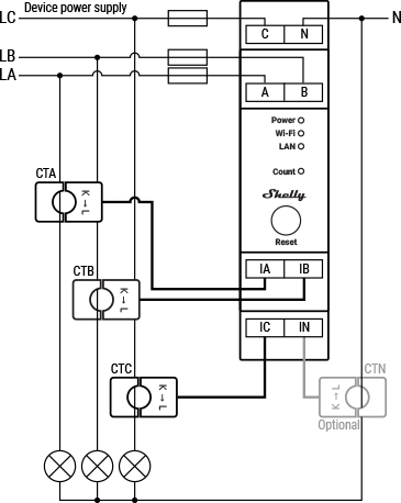
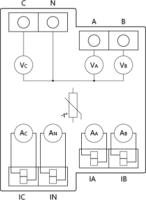
Emporia explicitly warns that anything connected to its main A/B/C ports will be treated as total usage. That means a perfectly healthy clamp can still create bad whole-home calculations if it is connected to the wrong class of port. Shelly's Pro 3EM documentation similarly shows that each CT input belongs to a specific phase-measurement role, not just a generic current slot.
This kind of error is easy to miss because the numbers may move in the app. They are just moving under the wrong label or boundary.
One of the strongest habits in professional monitoring work is to verify mapping immediately after energizing:
- Turn on one known load.
- Confirm that only the expected channel responds.
- Check the sign of the power value.
- Confirm the change appears on the expected phase or circuit name.
That five-minute check prevents a surprising amount of later rework.
5. The wrong measurement boundary creates the wrong story
A CT install can be technically correct and still be useless if it measures the wrong point.
This is less of a wiring mistake and more of a monitoring-design mistake, but it shows up constantly in retrofit projects.
Examples:
- A homeowner wants to understand why the power bill is high, but only monitors solar generation.
- A solar user wants self-consumption visibility, but only monitors total mains without a clean solar feed context.
- An EV owner wants to understand charger impact, but adds another whole-home graph instead of isolating the charger circuit.
The result is often a dashboard that looks rich but answers the wrong question.
That is why you should decide first whether the CTs need to measure:
- grid mains
- solar feed
- one major branch circuit
- a combination of whole-home and targeted circuit loads
If the measurement boundary is wrong, better app polish will not rescue the workflow.
6. Do not assume software correction replaces a clean physical install
Many platforms offer direction reversal, multipliers, or flexible labeling. Those features are useful. They are not a substitute for a disciplined install.
Software correction is best treated as:
- a commissioning convenience
- a way to avoid reopening a difficult panel when one simple reversal is otherwise confirmed
- a fine-tuning step after the physical install is already understood
It is not a good substitute for:
- guessing the phase mapping
- ignoring mixed-phase conductor issues
- skipping validation on a three-phase system
- leaving the install undocumented
IoTaWatt's guidance is especially useful here: automatic reversal may be acceptable convenience in some single-phase situations, but three-phase work still depends on correct orientation.
7. Small hardware issues still matter: closure, damage, and CT selection
Not every CT problem is about direction or mapping. Some are purely mechanical.
Emporia's support material notes that damaged CTs can create unreasonable or erratic readings, even if the outside of the sensor looks normal. Their guidance also distinguishes between different CT sizes and port types, because calibration expectations can change when you move between main ports and branch ports.
That means you should also check:
- whether the clamp is fully closed
- whether the ferrite core may have been cracked by rough handling
- whether the selected CT type matches the intended port and current range
- whether a flexible sensor or different clamp class is needed for the panel geometry
Good monitoring depends on more than "a clamp somewhere in the panel." The CT type, input role, and reference structure all matter to whether the resulting power and energy calculations stay believable.
If a channel still behaves strangely after conductor choice, direction, and mapping are confirmed, the next suspect is often the clamp hardware itself.
A practical install checklist before you close the panel
Use this checklist before treating the job as complete:
- Confirm each CT is on the intended conductor and not on neutral unless the system explicitly calls for a dedicated neutral CT workflow.
- Confirm the clamp is fully closed and physically secure.
- Confirm arrow or polarity direction against the platform's expected current flow.
- Confirm each CT channel matches the correct phase, circuit, and voltage reference.
- Confirm any multi-pole or three-phase circuit is being measured in the way the platform expects.
- Confirm the measurement boundary matches the business question: mains, solar, branch circuit, or mixed setup.
- Energize one known load and verify the expected channel, sign, and phase response.
That is a short checklist, but it catches most of the expensive mistakes before they turn into "data quality" problems later.
Bottom line
The most common CT clamp mistakes are rarely exotic. They are usually basic installation and mapping errors repeated in more complicated electrical contexts: the wrong conductor, the wrong direction, the wrong phase relationship, or the wrong measurement boundary.
For EnergyMeterHub readers, the real lesson is that good energy monitoring starts one layer earlier than many people expect. It starts not with dashboards or automations, but with a trustworthy measurement architecture.
If the CT layer is clean, the rest of the monitoring stack becomes much easier to trust. If the CT layer is wrong, everything above it becomes harder to interpret, no matter how polished the software looks.
Related reading
- What to Check Before Adding an Energy Meter to an Existing Solar System
- Main Meter vs Circuit Meter for Solar Homes: Which One Do You Actually Need?
- How to Monitor Solar, Battery, Grid, and Household Load Without Ending Up With Confusing Data
- How to Read Three-Phase Home Energy Data Without Getting Lost
- What an Open Energy Meter Lets You Do That a Closed App Usually Does Not
- Shelly Pro 3EM
- Emporia Vue 3 3-Phase Energy Monitor