An energy meter's accuracy class is useful, but it is not a complete statement of how accurate the installed monitoring system will be. Class 0.5S is usually the stronger choice for transformer-operated metering that must remain dependable at low current. Class 1 is often sufficient for general energy monitoring, load profiling, and non-billing submeters. The correct choice depends on the standard, connection method, current range, current transformers, and the decision the data will support.
That distinction matters because buyers often compare only the number on the front of the meter. A Class 0.5S meter connected through an unsuitable CT, configured with the wrong ratio, or wired to the wrong phase can produce worse data than a correctly installed Class 1 meter. Accuracy starts with the specification, but it is won or lost in system design and commissioning.
Quick decision guide
| Use case | Sensible starting point | What matters most |
|---|---|---|
| Home energy dashboard | Class 1 can be sufficient | Correct import/export direction, phase mapping, reliable data access |
| Solar self-consumption monitoring | Class 1 or better | Bidirectional energy, low-load behavior, consistent netting method |
| EV charger, heat pump, or equipment submeter | Class 1 for operational monitoring; verify local rules for cost allocation | Circuit boundary, meter range, installation quality |
| Commercial tenant allocation | Meter approved for the intended legal and contractual use | Applicable regulation, certification, sealing, audit trail |
| Main incomer with external CTs | Class 0.5S is a strong practical target | CT class, burden, ratio, wiring, low-current performance |
| Energy-performance verification | Class 0.5S or project-specified system accuracy | Traceability, calibration plan, synchronized comparison data |
| Utility or revenue metering | Only the class and approvals required by the authority or contract | Legal metrology, approved meter/CT combination, installation rules |
This table is a selection shortcut, not a substitute for the project's specification or local metering rules.
What an accuracy class actually tells you
An accuracy class places the meter inside a defined error envelope under the test conditions of a named standard. It is not a universal promise that every displayed current, power, and energy value will always be within the class number as a percentage.
Two current IEC standards are especially relevant:
- IEC 62053-21:2020 covers static meters for AC active energy in Classes 0.5, 1, and 2.
- IEC 62053-22:2020 covers transformer-operated static meters for AC active energy in Classes 0.1S, 0.2S, and 0.5S.
The standards define class-specific requirements across current ranges and test conditions. They also sit alongside general requirements and test methods in the IEC 62052 series. That is why a data sheet should state both the class and the standard. A bare claim such as "0.5% accurate" does not provide the same assurance.
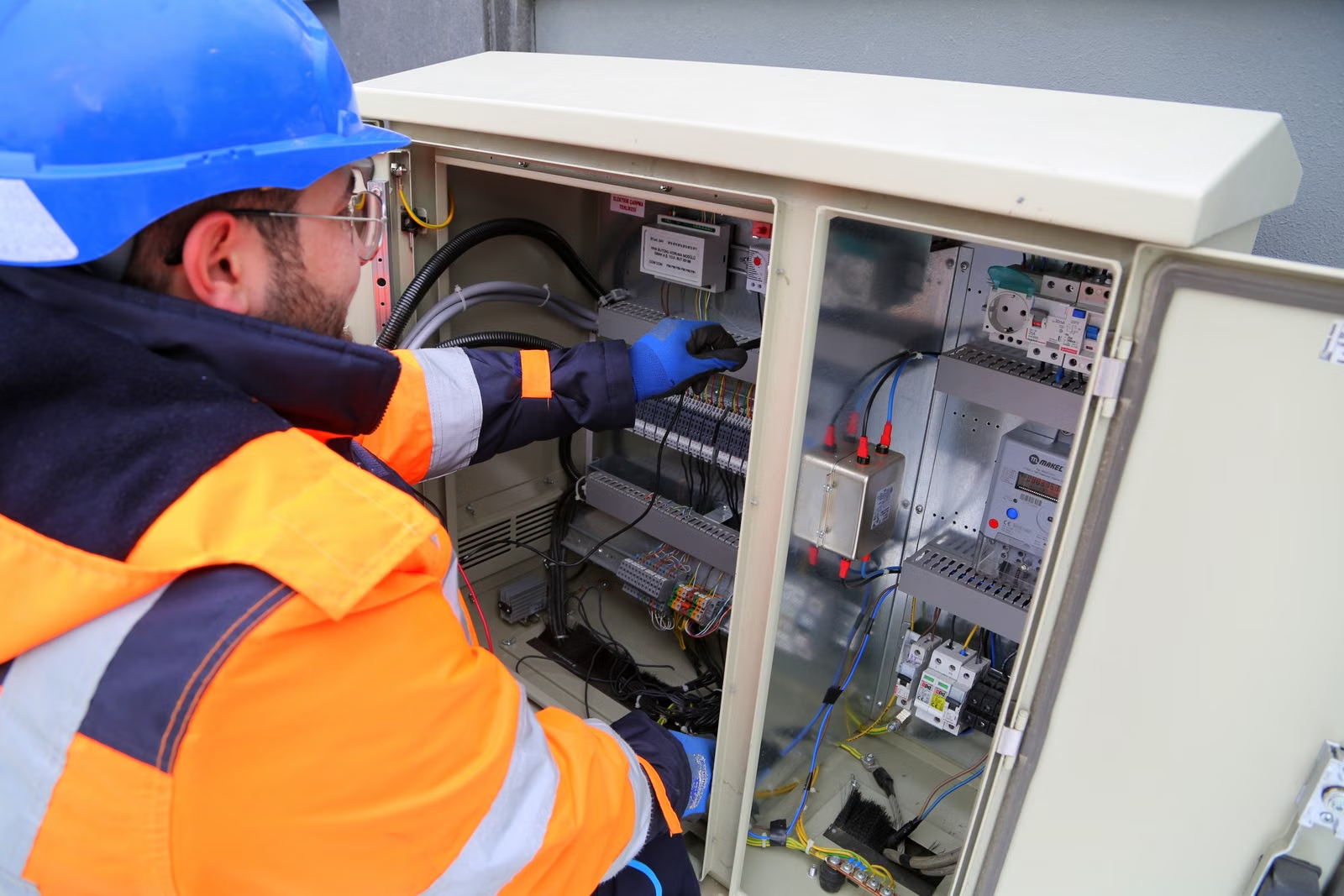
Meter accuracy is a system property in practice. Photo by Fatih Yurtman via Pexels.
Class 0.5S vs Class 0.5 vs Class 1
The most important point is that these labels are not interchangeable marketing tiers.
Class 1
Class 1 active-energy meters are widely used for operational monitoring and submetering. They can be a good fit when the goal is to:
- Find when energy is being used
- Compare daily or monthly consumption
- Track a large individual load
- Monitor import and export trends
- Feed a building dashboard or home automation system
- Identify abnormal baseload or equipment schedules
For these uses, a consistent measurement boundary and correct installation often matter more than paying for a tighter class.
Class 0.5
Class 0.5 under IEC 62053-21 applies to the meter category covered by that standard. It offers a tighter class than Class 1, but buyers must still check the declared current range, connection type, and exact model certification. Do not assume that every product advertised as "0.5" behaves like a 0.5S transformer-operated meter at low current.
Class 0.5S
IEC 62053-22 applies to transformer-operated meters, including Class 0.5S. The "S" class is particularly relevant where a CT-operated system must maintain controlled performance across a wider practical current range, including relatively low current.
That makes 0.5S attractive for commercial incomers, industrial feeders, multi-site energy management, verification work, and installations where overnight or lightly loaded periods still matter. It is also common in meters designed for 1 A or 5 A CT secondary inputs.
A lower class number does not repair a poor design. It only gives the project a better meter-level starting point.
Why low-current performance can change the decision
Many sites spend long periods far below peak demand. An office may draw heavily for eight hours and lightly overnight. A solar facility may move from high daytime flows to low auxiliary loads after sunset. A residential building may have a large service rating but only a small baseload for much of the day.
Suppose a 400 A incomer normally runs at 20-80 A outside short peaks. Selecting the meter and CT only around the 400 A maximum can leave most energy accumulation near the lower end of the measurement chain. In that case, low-current behavior can be more important than the headline maximum.
This is where the complete specification matters:
- Starting current
- Minimum current
- Transitional current
- Nominal or reference current
- Maximum current
- Accuracy limits across those regions
- Power-factor test conditions
- Temperature and electromagnetic influence requirements
A meter can display a live number below the range where its best accuracy is guaranteed. "It reads something" and "it meets the class requirement here" are different statements.
The meter is only one part of a CT-operated system
For a CT-operated meter, the measurement chain includes at least:
- The primary conductor
- The current transformer
- CT secondary wiring and terminals
- The meter's current input
- Voltage inputs and phase references
- Configuration such as CT ratio and wiring mode
- The data path to the dashboard or billing system
Each element can add error or create a much larger mistake.
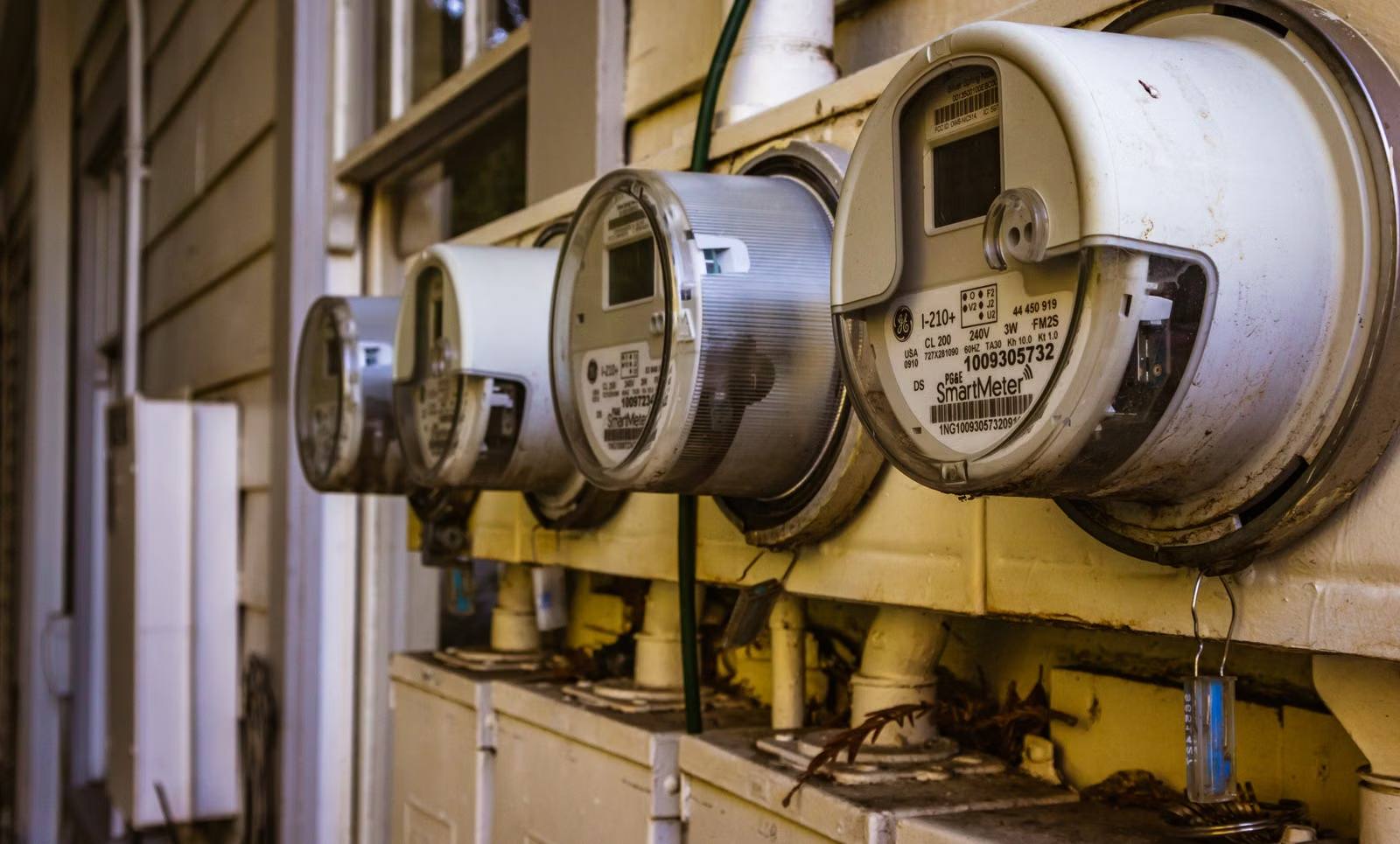
Similar-looking meters may have different ratings and approvals. Photo by Robert So via Pexels.
CT class and ratio
The CT must be suitable for measurement, not merely protection. Its ratio should match the expected operating current, not just the largest conductor or protective-device rating. An oversized CT may spend too much time at a small fraction of rated current.
For example, a 600/5 A CT on a feeder that usually carries 20 A produces only about 0.167 A on the secondary. Whether the complete system performs well there depends on the CT specification, meter input, burden, and applicable accuracy range.
Burden
A conventional CT is designed to work within a stated burden. The meter input, secondary cable resistance, terminals, and any other series devices contribute to that burden. Schneider Electric's CT accuracy guidance notes that meter and cable burden must remain within the CT's specified limit for the claimed class.
Long, undersized secondary wiring can therefore undermine an otherwise good selection. CT secondaries also require appropriate safety practices and must not be opened while energized.
Phase angle and phase pairing
Energy and power depend on both magnitude and phase relationship. If a current input is paired with the wrong voltage phase, the readings can be drastically wrong even when voltage and current values each look plausible. Low power factor can also expose phase-angle error more strongly.
Ratio and wiring configuration
A wrong CT ratio creates a proportional scaling error. Configuring a 400/5 A CT as 200/5 A will not create a subtle class-level discrepancy; it will roughly halve the reported current and energy. Selecting three-phase four-wire mode for a different wiring arrangement can produce equally serious problems.
Meter class is not the same as every parameter's accuracy
A product may claim Class 0.5S for active energy while specifying different accuracy for:
- Active power
- Reactive power and energy
- Apparent power and energy
- Voltage
- Current
- Power factor
- Frequency
- Total harmonic distortion
For example, Schneider Electric's EM6400NG+ specification lists parameter-specific classes and errors rather than one figure for everything.
This distinction matters when the project is diagnosing voltage quality, power factor, or harmonics rather than only accumulating kWh. An energy class alone does not make a meter a power-quality analyzer.
IEC classes and MID classes are different frameworks
In the European Union, the Measuring Instruments Directive (MID) defines Classes A, B, and C for active electrical energy meters intended for residential, commercial, and light-industrial use. Annex V of Directive 2014/32/EU sets rated operating conditions, maximum permissible errors, disturbance requirements, and conformity-assessment routes.
Do not translate MID A/B/C and IEC 62053 class labels by the number alone. A manufacturer may document how a product complies with both frameworks, but the project should verify the exact meter variant, approval marking, certificate, and permitted use.
This is especially important when readings are used to allocate energy costs, bill a tenant, support a regulated transaction, or settle a contract. A technically accurate monitor is not automatically approved for billing.
When paying for 0.5S makes sense
A 0.5S meter is easier to justify when one or more of the following are true:
- The meter is CT-operated and the load varies over a wide range
- Low-load energy is material to the annual total
- Small differences drive operational or contractual decisions
- The project compares measured savings before and after an upgrade
- Several submeters must reconcile closely with a main meter
- Data is used across multiple sites and must be consistently auditable
- The installation has a documented calibration or verification program
- The cost of investigating unexplained discrepancies is high
The premium is harder to justify when the main purpose is finding broad trends, switching schedules, or detecting whether a large load is on. In those cases, data availability, correct installation, and usable software may create more value than moving from Class 1 to 0.5S.
A practical error example
Assume a feeder truly consumes 100,000 kWh in a year. A simple headline calculation might suggest:
- 1% equals 1,000 kWh
- 0.5% equals 500 kWh
That comparison is useful for estimating stakes, but it is not a prediction of actual error. The standard's limits vary with current and test conditions, while the installed system adds CT and wiring effects.
The business question is therefore not "Is 0.5S twice as accurate?" It is:
Would a tighter, properly engineered measurement chain change a decision enough to justify its additional cost?
If energy is valued at $0.20/kWh, 500 kWh is worth $100 in this illustrative scenario. For a single small feeder, that may not justify a complex upgrade. Across hundreds of meters, or where discrepancies trigger disputes and site visits, the lifecycle value can be much larger.
How to read a meter data sheet before buying
Use this checklist:
1. Identify the exact measurement standard
Look for the full reference, such as IEC 62053-21 or IEC 62053-22, not just "high accuracy."
2. Confirm direct or transformer operation
A direct-connected DIN-rail meter and a 1 A/5 A CT-operated meter solve different installation problems.
3. Check the complete current range
Record starting, minimum, nominal or reference, transitional, and maximum current where provided.
4. Match the electrical system
Verify single-phase or three-phase, three-wire or four-wire, voltage range, frequency, and supported wiring modes.
5. Separate energy accuracy from other measurements
Check active energy, active power, reactive energy, voltage, current, power factor, and harmonics individually.
6. Confirm bidirectional behavior
For solar, batteries, and regenerative loads, verify import/export registers, four-quadrant behavior, phase netting, and sign conventions.
7. Verify approval for the intended use
Check the exact order code and certificate. Product families often mix approved and non-approved variants.
8. Review communication details
For Modbus, M-Bus, pulse, Ethernet, or wireless integration, confirm update rate, register map, data types, scaling, and whether cumulative energy survives outages.
9. Include CTs in the specification
Specify ratio, class, burden, aperture, secondary rating, cable run, and installation orientation.
10. Plan verification before procurement
Decide how the meter will be checked against a known load, reference instrument, upstream meter, or energy balance.
Commissioning: where accuracy becomes trustworthy
A good commissioning process should test more than whether the display turns on.
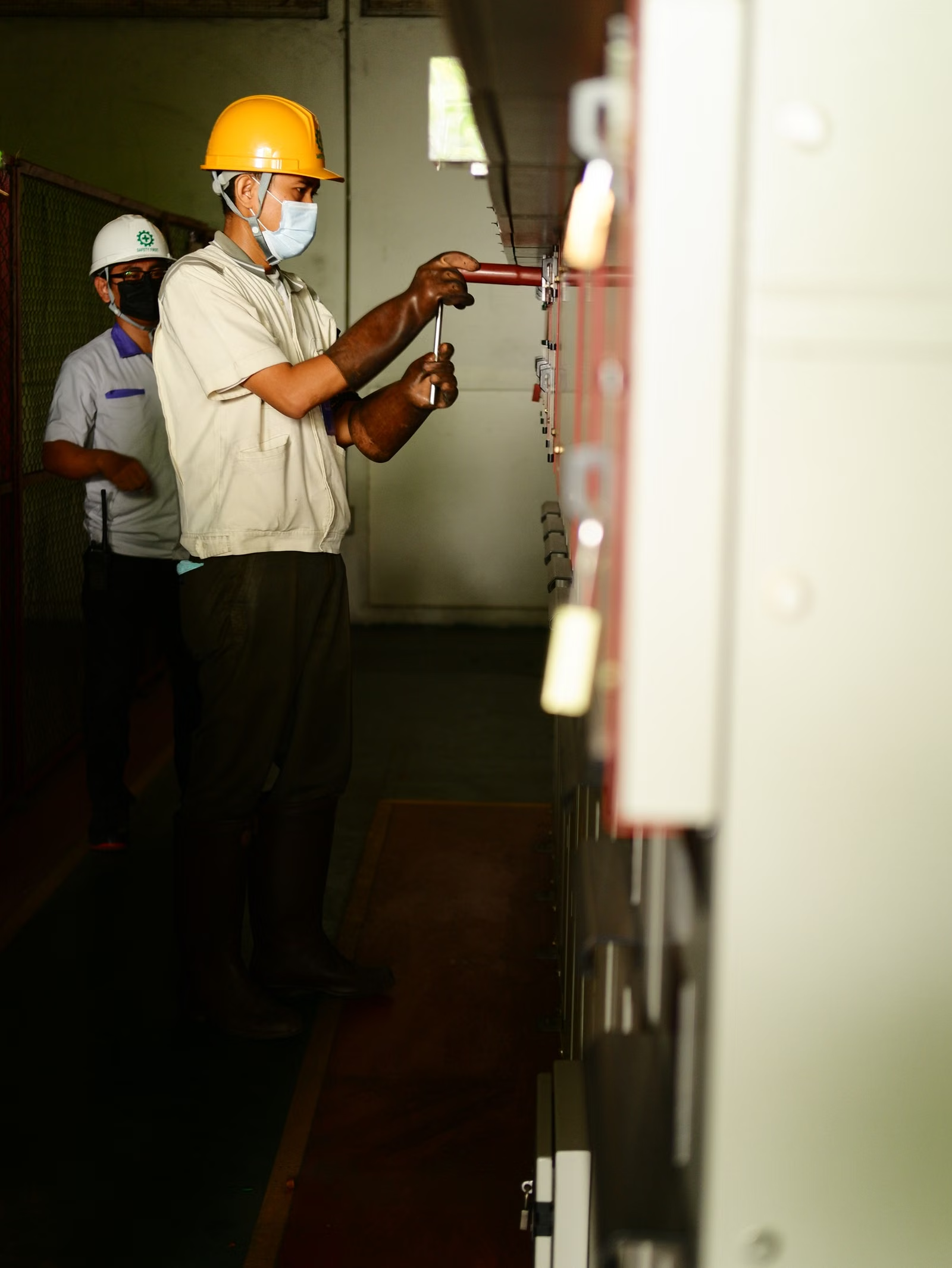
Commissioning should verify phase pairing, direction, ratios and data mapping. Photo by Annas Zakaria via Pexels.
- Record nameplate data. Capture the exact model, serial number, firmware, class, standard, CT ratio, and wiring diagram.
- Check phase pairing. Confirm each current input corresponds to the correct voltage phase.
- Check CT polarity and direction. Apply a known load and verify expected import or export direction.
- Check scaling. Compare primary current with the meter reading and confirm the configured ratio.
- Test a known load. A stable resistive load provides a useful first check, although it is not a calibration.
- Compare cumulative energy. Run the known load long enough to create a meaningful kWh increment.
- Test low load. Confirm that overnight or standby conditions are visible and credible.
- Test bidirectional operation. For solar or batteries, observe importing and exporting states.
- Validate communications. Compare the local display with protocol registers and the final dashboard.
- Document uncertainty. State whether the result is a functional check, field comparison, or traceable calibration.
For formal verification, use qualified personnel and suitable reference equipment. A handheld clamp meter with unspecified or incompatible accuracy is not proof that a revenue meter is wrong.
Common buying mistakes
Avoid these shortcuts:
- Choosing solely by the lowest class number
- Treating meter accuracy as installed-system accuracy
- Assuming 0.5 and 0.5S are the same category
- Using a protection CT for precision metering without checking its specification
- Oversizing CTs around rare peaks
- Ignoring cable burden on 1 A or 5 A secondary circuits
- Assuming MID approval applies to every variant in a product family
- Using active-energy class to infer harmonic or power-quality performance
- Skipping phase and polarity tests because the dashboard looks plausible
- Comparing two meters that use different phase-netting or import/export logic
Bottom line
Choose Class 1 when you need dependable operational insight and the financial or engineering decision does not require tighter system performance. Choose Class 0.5S as a strong starting point for CT-operated installations with wide load variation, meaningful low-current energy, reconciliation requirements, or formal performance verification.
Then spend at least as much attention on the CTs, wiring, configuration, communications, and commissioning as you spend on the class printed on the meter. The best accuracy class cannot rescue the wrong measurement boundary, but a well-designed system can turn a sensible meter into trustworthy data.
Sources
- IEC 62053-21:2020: static meters for AC active energy, Classes 0.5, 1 and 2
- IEC 62053-22:2020: transformer-operated static meters, Classes 0.1S, 0.2S and 0.5S
- EU Measuring Instruments Directive 2014/32/EU, Annex V
- Schneider Electric EM6400NG+ measurement specifications
- Schneider Electric: how CT accuracy class and burden are calculated
- Schneider Electric: what the S means in Class 0.2S and 0.5S